







PV
Optical Array
PV 18.6 MW
ENERGY MANAGEMENT PLATFORM
From operating targets to device commands,
form a verifiable energy-management closed loop
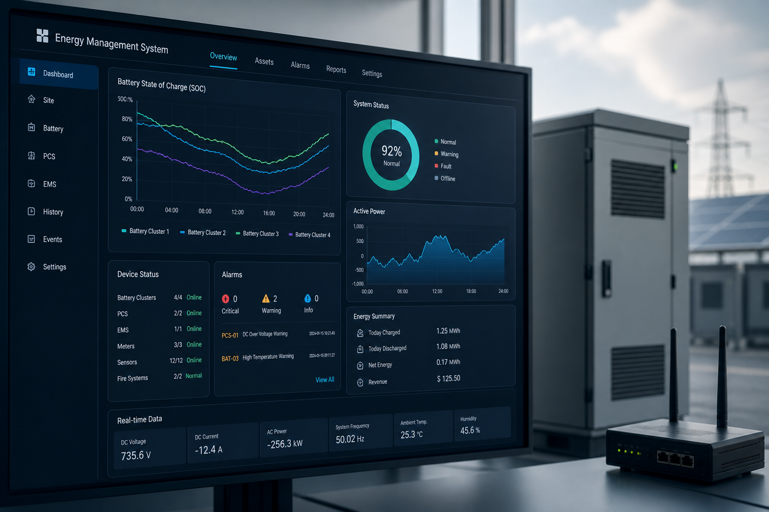
Station-level EMS unifies load, PV, grid requirements, equipment availability, and storage boundaries in one operating framework—from day-ahead planning and intra-day adjustment through PCS, BMS, and field execution—then confirms every command landed via measurement feedback.
The optimizer determines how " it wishes to run " and EMS is responsible for converting it to a secure, defined, enforceable and verifiable device action.
TR
step-up transformer
Transformer 33 / 110 kV
BESS
Energy Storage Systems
BESS · SOC 62.4%
PCS
PCS Conversion System
Two-way power control
MAIN
Main transformer
Transformer 110 kV
GRID
Grid Connection Status
Grid 110 kV
Current mode of operation
Peak Reduction
Policy: PAAK SHAVING
Site Load
42.7 MW
Real time measurements
The light works.
18.6 MW
Act in real time.
Storage Power
-16.2 MW
Power discharge.
SOC
62.4%
System average
Available backup
8.6 MW
Organisation
Network power
-24.3 MW
Negative: Sending electricity to the grid
Network frequency
50.01 Hz
&Normal
01 First define the running target, then decide how the storage can move.
Peak Reduction
Reduce site peak and limit maximum demand
Optical self-maximum
Improved local use of new energy sources
Demand management
Control of contract requirements and grid-connected power
Standby capacity
Guaranteed reconciliation capacity and recovery residuals
Grid Response
Participate in FM/ dispatch/ support services
Peak reduction:
Subject to SOC, equipment power, grid and reserve boundaries, station peak loads are limited to the set target.
02 Any movement must be subject to the equipment and station. Constraint to decide which plan is the plan to implement.
SOC
SOC Window
Allowed energy range
20% – 90%
P
The PCS has power.
Charge / discharge power boundary
-25 → +25 MW
Q
PCS incompetence
Power factor / no power constraint
-25 → +25 Mvar
POI
Network power limit
POI Double Power Boundary
-40 → +40 MW
T
Ambient temperature
Thermal management and reduction basis
-10 → 45°C
HA
Availability of equipment
Runable Unit Pool
≥ 96%
SOC window:
Plan SOC remains within the controlled window and must set aside the upper and lower limits required for equipment protection and backup capacity.
03 · forecast → plan → dispatch → feedback → correct, forming a closed loop
A 24-hour scroll-axis: All inputs, plans, instructions and feedback use a uniform time frame.
Load forecast
Photovolt prediction
Time price of electricity
Network power
Storage Power
Standby capacity target
Schedule Command
Actual feedback
04 Previous planned and daytime dispatch desk
Plan Generation
05-19 16:20
05-19 16:20
Ban the core.
05-19 16:28
05-19 16:28
Programme evaluation
05-19 16:35
05-19 16:35
Manual confirmation
05-19 16:40
05-19 16:40
Release Execution
05-19 16:42
05-19 16:42
05 Command link: certainty closed loops from EMS to executive level
CMD-20250520-0132
Pset = -16.0 MW
Temperature 31°C
Allow Run
-412 A
-16.1 MW
Principle of certainty:
EMS's “request sent successfully” is not completed. The final state must be confirmed jointly by PCS response, BMS clearance, equipment action and independent measurement feedback.
06 Mode Switches to Priority Award
1
Security priority
Equipment security, electricity grid security, fire protection and protection
2
Contract / grid constraint
Networking restrictions, back-up and response commitments
3
Previous schedule
Plan power and energy targets
4
Intra-day dispatch
Real time correction and scheduling instructions
5
Local optimization of equipment
SOC balanced, efficient, heat management
| Run Mode | Core objectives | Typical conflict | Storage action |
|---|---|---|---|
| Peak Reduction | Lower Peak | There's not enough backup. | Controlled discharge |
| Photovoltaic. | Increase in the rate | SOC ceiling | First Charge |
| Requirement Control | Limit grid power | Power capacity | Peak / Hollow |
| Grid Response | Tracking command | Equipment protection | Protection priority |
| Equipment constraints | Protection equipment | Economic objectives | Decrease / Stop |
Normal
Target Switch
Binding trigger
Policy Switch
Command Amendment
Restoration of stability
• Each power directive must leave reversible evidence of execution
Plans, commands, permissions, execution, and measurement results are linked by one Command ID.
PEAK_SHAVING_v3.2.1
-16.0 MW
Allow Run
-412 A
-16.1 MW
08 Strategic governance: from configuration to continuous optimization
09 Border description
✓
Scope of this page: Site-level EMS operational objectives and strategy implementation
✓
Current / Day plan receipt and adjustment
✓
Real-time restraint management of equipment and sites
✓
Instructions issued, permission checks and execution closed loops
✓
Operational strategy and version governance
Station level EMS
Implementation and coordination level
Implementation and coordination level
Multi-target command and capability coordination
• Optimization and strategy platform
• Optimization and strategy platform
Run performance and deviation closed loop
• Performance analysis platform
• Performance analysis platform
×
Not on this page: Market-level transaction optimization
×
Not on this page: Transregional grid movement
×
Not on this page: electrochip level protection control
×
Not on this page: Long-term asset lifetime projections
×
Direct control without bypassing PCS / BMS
Principles of responsibility:
The Optimization and Strategy Platform is responsible for “calculating better targets”, the EMS is responsible for “translating targets into safe and implementable equipment behaviour”, the PCS/BMS is responsible for equipment-level control and protection, and the Performance Analysis Platform is responsible for validating the results of the plan.