
1
Requirements confirmation
Confirm application scenarios and performance needs; define project capacity and operating objectives.
Confirm application scenarios and performance needs; define project capacity and operating objectives.
Configuration cells, modules, packs, racks, BMS, and thermal-control schemes.
The specifications for electrical, communications, liquid cooling, fire protection and mechanical interfaces are officially frozen.
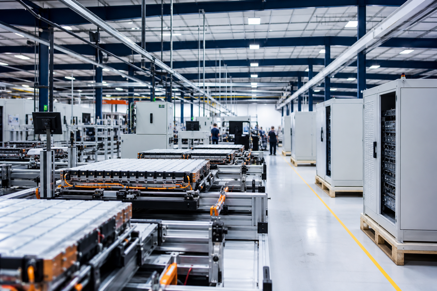
Key process manufacturing, process inspection and complete certification of the FAT plant.
Uniform confirmation of mode of transport, packaging, protection and conditions of shipment.
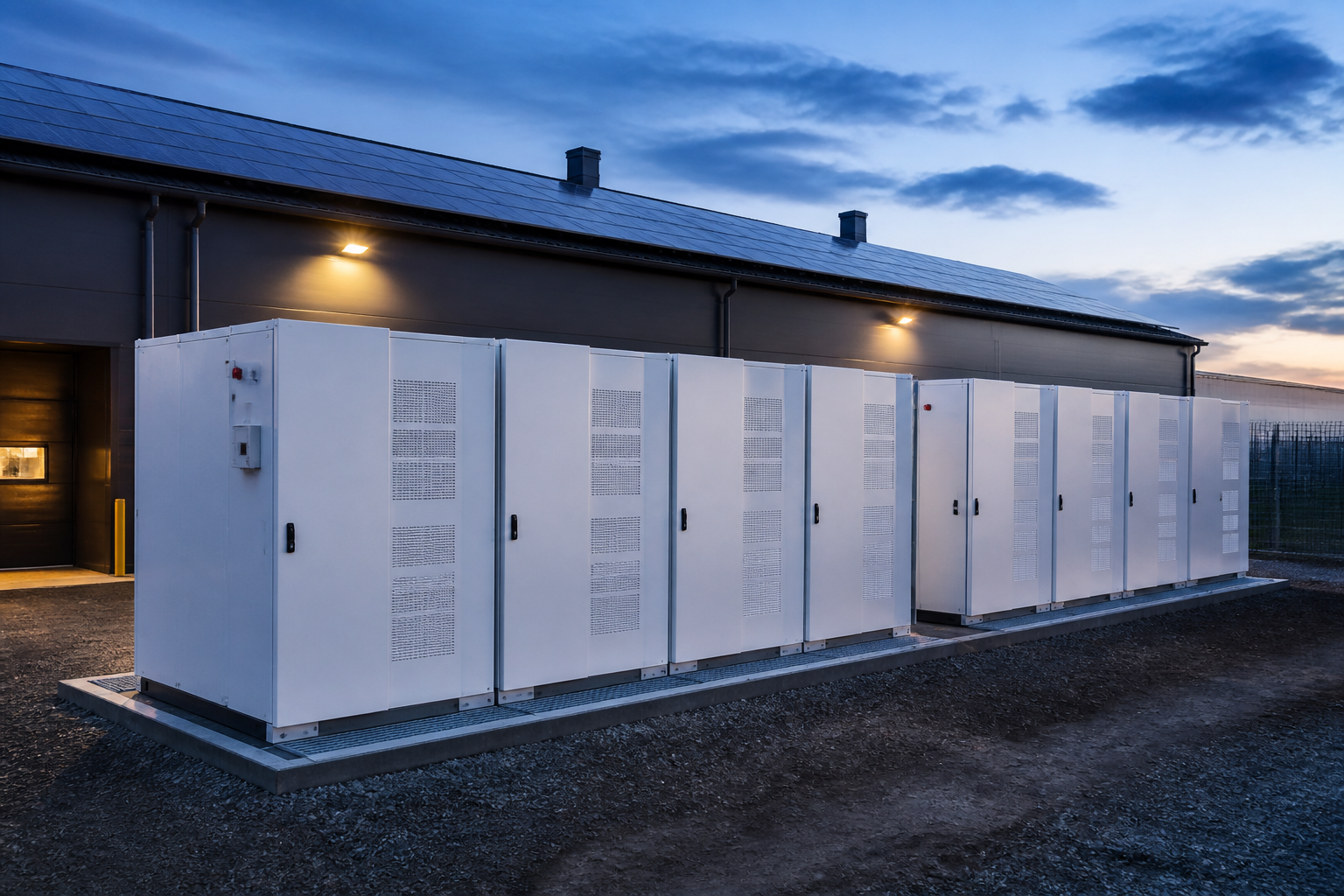
Arrival acceptance, equipment position, interface connection and integration support.
| Interface category | Key parameters / signals | TIANCHU range (battery systems) | Client/ EPC Side Interface | Interface location | Status |
|---|---|---|---|---|---|
| Electrical (DC) | Voltage range / rated current / max current | DC 560–1500V / DC busbar and protection | Connect to PCS DC side | DC Block Output Master | Freezed |
| Cooling interface | Medium / temperature range / flow / pressure drop | Liquid Cooling Systems and Internal Access | Access to customer cooling systems | Cool it and give it back. | Freezed |
| BMS & Communications | CAN 2.0 / 250 kbps / Status and Police | BMS, Communications Interface and Signal Definition | Access EMS / PCS | Communications End Line | Freezed |
| Fire signal. | Warning / Fault / Link / Reset | Battery system internal fire. | Access to client fire control systems | Fire signal end. | Freezed |
| Machinery and Foundation | Size / Weight / Install Hole | Device capital and suspension interface | Basic and installation conditions | Basic Install Interface | Freezed |
| Local | Protect local/ level connections | PE access / internal connection | In-site network of access stations | Local End | Freezed |
| Transport and services | Fix Channel / Operating Space / Light | Space definition for equipment overhaul | On-site conditions met. | Site setup | Freezed |
| Working matters | TIANCHU (battery systems) | Client (owner) | EPC Total | Joint (TIANCHU & Client/EPC) |
|---|---|---|---|---|
| Battery system design and construction | R | I | I | - |
| PCS (including control protocols) | - | R | R | - |
| EMS / Energy Management | - | R | R | S |
| transformer / switch system | - | R | R | - |
| DC / AC cables and busbars | R | R | R | S |
| Land-building infrastructure | I | R | R | S |
| Equipment transport (carrying) | R | I | S | - |
| BESS installation and location | S | R | R | S |
| System connection (Battery + PCS) | R | R | R | I |
| Fire connections and acceptances | S | R | R | S |
| Connect station/ deliver acceptance | I | R | R | S |
| Operation maintenance (under warranty) | R | R | - | S |
| Item | Interface requirements | Our supply capacity / Match | Authentication Method | Status |
|---|---|---|---|---|
| Direct current voltage range | Range: 960-1500 V | Support 960-1500 V to meet system design boundaries | FAT Test | Pass. |
| Precharge | Precharging current/ time | 100A / 60s, as project configuration | FAT Test | Pass. |
| Insulation monitoring | Seal / Breaker Conditions | Meet DC PCS-side insulation and safety-interlock requirements | FAT Test | Pass. |
| Power commands and limit values | P-command / restricted flow / limit pressure | Support PCS command, limit and state closed loop | Integrated Test | Pass. |
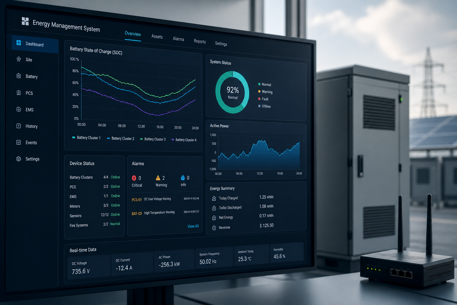
| Alarms and status | / Serious Level | PCS alert, failure and operational status | Integrated Test | Pass. |
| Emergency shutdown. | Hardware E-Stop/ Chain Road | Support e-stop and safety-interlock signals | FAT Test | Pass. |
| Logic of trouble management | Report failure / quarantine / reset | Support for failure containment, status reporting and repositioning | Integrated Test | Pass. |
| Test Project | Test Conditions | Result |
|---|---|---|
| Functional Validation | 100% Functional Override | Pass. |
| Insulation. | 1500VDC | Pass. |
| Direct electrical performance | 0.5C / 1C | Pass. |
| Communication Protocols | BMS & CAN | Pass. |
| Liquid Cooling System | Flow / Pressure | Pass. |
| Performance Validation | Capacity / Efficiency | Pass. |
| Test Project | Test Conditions | Result |
|---|---|---|
| Link to PCS | Energy interaction | Pass. |
| Power Response | ±100% Pn | Pass. |
| Protection coordination | Alarm / interlock | Pass. |
| Alarm interlocking | Alarm triggered | Pass. |
| Emergency shutdown. | E-Stop | Pass. |
| Check on-line | Interface integrity | Pass. |
Configuration transport protection and packaging programmes by size, weight and equipment characteristics.
Uniform inspection of appearance, quantity, documentation and transport injuries.
In situation, installation, liquid cooling, communications and electrical connections are performed by interface.
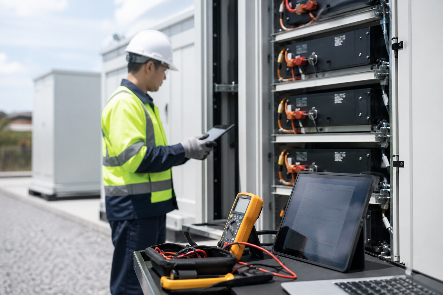
Installation guidance, interface inspection and confirmation of conditions for on-site delivery.
Size: 100 MW / 215 MWh (battery system straight-stream)
Scope of supply: Battery cabinet, DC Block, BMS, Liquid Cooling Systems interface with fire protection
Boundary position: DC Block Output Master
Delivery mode: Battery System Supply+ Interface Freeze + Integrated Support
Identification of boundaries and interfaces to accelerate project integration and delivery