


Integrated lithium battery energy storage solutions
DEMO PROJECT

Controlled deployment of a 2.61 MWh multi-cabinet energy storage system for an industrial park

Project ID: TC-DEMO-PROJ-CI-2610
E
2.61MWh Total energy
P
1.25MW Rated power
AC
AC 690V Grid-connection voltage
RUN
OPERATING Run Status

Project challenges

In the limited-occupied industrial parks, the boundaries of the existing production networks and plants, the construction, installation of equipment, electrical access, fire-fighting connection and netting are completed, while minimizing the impact on existing production.

1
Limited site area: The available space is small and only about 38m x 22m.
2
Production continuity: Production continued during the construction, with a phased controlled switch.
3
Electrical capacity: Connection points are restricted and access is controlled by 1.25 MW.
4
Noise control: ≤ 65 dB(A)@1m.
5
Fire escape: 4m Fire access and equipment clearances.

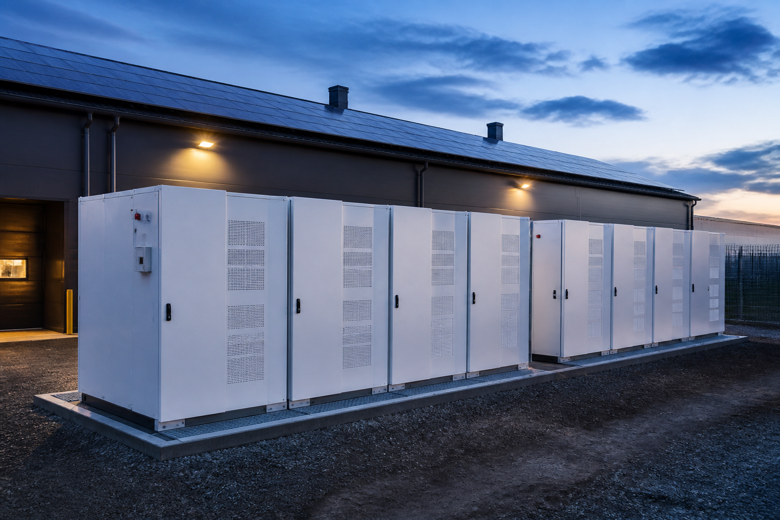
Ten cabinets arranged in two blocks. (total energy 2.61 MWh)

Area A (5 cabinets) 01 02 03 04 05 PCS Box Transformer / Power Distribution Fire cabinet. Area B (5 cabinets) 01 02 03 04 05 PCS Box Transformer / Power Distribution Fire cabinet. Fire Access 4.0 m 38.0m 22.0m Liquid-cooled Battery Cabinet(261kWh) PCS Box (1.25 MW) Transformer / Switchgear Fire-fighting facilities

Electrical primary single-line diagram (AC 690V)

System parameters

Battery cabinet scale 261kWh Liquid-cooled Battery Cabinet × 10
Battery chemistry LFP
Total energy 2.61 MWh
Rated power 1.25 MW
Grid-connection voltage AC 690V / 3P4W / 50Hz
PCS Top Three-level topology, liquid cooled
System configuration Two-zone layout, independent PCS, centralized grid connection
Ingress protection IP55 (battery cabinet) / IP54 (PCS cabinet)
Operating temperature -20°C – 50°C
Communication Protocols IEC 61850 / Modbus TCP

Controlled Construction and Grid Connection: Switching done under continuous coordination with plant operations

From the design freeze, on-site work to the eventual transmission of electricity to the grid, conditions and engineering evidence are clearly documented at every stage.

01
Isolation program confirmed. Power outage window confirmed.
02
On-site construction Partition operations
03
Equipment in position. Delivery by day
04
Electrical connection Night Window
05
System check Locks/ Parameters
06
Electrified. Controlled Switch
Construction windows within the plant
FAT complete.
Container transport
Hanging.
Ten cabinets in position.
Integrated commissioning and acceptance

System integration and coordinated protection

EMS
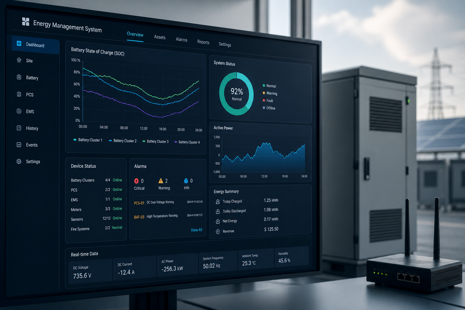
EMS Policy Integrate with the plant energy-management platform to support peak-shaving plans, energy management, and strategy dispatch.
PCS
PCS Control PQ control, V/f support, power limit, rapid response 200 ms.
BMS
BMS Management Data monitoring, SOC/SOH estimation, balance and protection management.
SAFE
Protect and Link Overpressure / low pressure / insulation / smoke sense / locking out, working with fire and park systems.

SAT validation results Critical capabilities

Power tracking (1.25 MW step)

System Efficiency Curve (25°C)

Battery cabinet temperature differential (full power running)

OCSS (SAT phase)

Closed 100%
● Closed loop 100.0%
● Unclosed circle 1.0%
T
Controlled Switch Window 28 min
R
Maximum Volatility -1.2% / 10ms
P
Power tracking error ≤ ±1.0%
η
System efficiency (0.5C) 95.6%
SAT
Availability (SAT) 100%

Operation performance: a typical working day, peaking in load

1 & nbsp; & nbsp; load curve (plant area)

2    Schedule Command (EMS)

3    Battery response (actual)

4    peaking effect (connection point)

Run Evidence

Run Date 2024-05-18
Peak power 2.87 MWh
Maximum Peak Power 612 kW
Long discharge time 3.6 h

Availability (date)

99.8%
Available time: 23.95 h
Not available: 0.05 h

Maintenance of records

BMS Health Check &Normal
PCS Inspectorate &Normal
Fire system self-inspection &Normal
Environmental system operation &Normal

Change management

Change of date 0 items
Outstanding changes 0 items
Risk events 0 rise

Delivery: complete handover of works and responsibilities

Delivery package

  • Design drawings (A3 sets)
  • Equipment description & spare parts list
  • FAT/ SAT report
  • Wiring diagrams and point lists
  • EMS Policy Document
  • Transport Manual (C/ E)

Debug Report

  • FAT Report
  • SAT report
  • Insulation test report.
  • Protect Synopsis Report
  • Fire Union Test Report

Training Delivery

  • System theory
  • Transport
  • Fire and Emergency Trading
  • Emergency drill guidance

Quality assurance and services

  • 5 years of complete quality assurance
  • Battery quality assurance 10 years or 6000 cycles
  • 7×24 Remote Support
  • Spare parts and On-site Support

Transfer of responsibility

  • Transfer of system operation completed
  • Control transfer complete.
  • Transfer of documentation completed
  • Transfer of spare parts completed

Large-scale energy projects, and the reservoirs are delivered with engineering capabilities and controlled delivery.
Guarantee the stability and value of industrial sites.

From demand, integration, construction, and net delivery to long-term transport, complete and verifiable engineering closure.