


BMS Configuration|Projectized delivery
Write battery boundaries into control logic — every state visible, every protection traceable
BMS configuration · projectized delivery for sampling topology, estimation, thresholds, state machines, diagnostics and parameter versioning.
Demo project card TC-BMS-26-031 Demo data
- Topology
- 52S · 16 modules / Rack
- Firmware
- FW-B3.6 demo
- Param set
- PS-B3.6-R04
- SOC OK
- Insulation OK
- Fault Clear
- HIL 92% PASS
-

Precise sensing & topology map
Cell-to-system channel ownership.
-

State estimation & health
SOC / SOH / SOP / SOE with bounds.
-

Protection logic & state machine
Thresholds, debounce, HIL-proven.
-

Collaborative control & versioning
PCS / EMS linkage and param release.
Configuration input panorama
Nine project inputs that bound the BMS parameter set
- Topology Series / parallel · module & Rack map
- Sampling V / T / I channel counts
- Contactors Main · pre-charge · aux feedback
- Insulation / HVIL IMD thresholds · interlock
- Thermal / fire Cooling · derate · fire hooks
- PCS / EMS protocols CAN / Ethernet ICD
- Operating states Charge · discharge · standby
- Diagnostics Fault codes · logs
- Environment Ambient · altitude · site class
Three-tier network — BMU → BCU → System BMS
Cell sensing, Rack control and cabinet authority stay layered Demo data
BMU
- Cells / BMU
- 52 demo
- NTC / module
- 4–N
- Uplink
- Daisy-chain
- Balance
- Passive demo
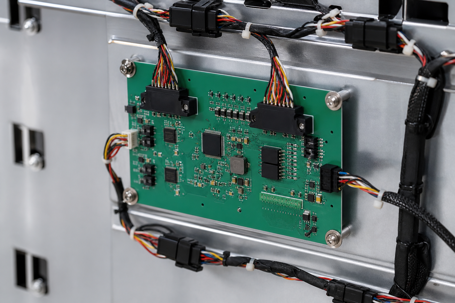
System BMS links
- PCS Power authority
- EMS Dispatch / schedules
- Fire Hardwire + alarm
- Cloud Telemetry optional
- Sense V / T / I
- Control Contactors / relays
- HV Interlock path
- Redundant Backup link
Traceable signal chain
Every measurement point must map to one traceable signal chain
Nine steps from sensor to event record · demo Demo data
- Sensor Cell / NTC / shunt
- AFE Front-end IC
- BMU MCU Local filter
- Bus Daisy / CAN
- BCU Rack fuse
- System BMS Authority
- Logic Threshold / SM
- Actuator Contactor / PCS
- Event log Trace ID
Channel link sample
| Channel | Source | Path | Consumer | Trace ID |
|---|---|---|---|---|
| Cell V[01] | BMU-A1 | AFE→BMU→BCU | SOC / OV | TR-V-001 |
| NTC[M3] | BMU-A3 | AFE→BMU→BCU | OT / derate | TR-T-014 |
| Pack I | Shunt | AFE→BCU | OC / SOP | TR-I-001 |
| HVIL | Loop | Hardwire→Sys | Interlock | TR-H-001 |
State estimation & health assessment workspace
Four aligned cards — metrics, curves, insulation/thermal, model metadata Demo data
- SOC 62.4% ±2.5% demo
- SOH 97.1% Capacity fade
- SOP 0.85 C Charge clamp
- SOE 148 kWh Usable
Model + measurement correction
OCV table + EKF residual · demo spark
Insulation & thermal state
- IR
- > 2 MΩ demo
- ΔT cell
- ≤ 3 K
- Coolant
- In range
Model & calibration metadata
- Algo
- EKF + OCV REV-D
- Cal date
- 2026-W30
- Owner
- BMS eng. demo
Executable state machine
Allowed transitions as solid paths · forbidden as dashed · demo Demo data
- POWER OFF
- INIT
- STANDBY
- PRECHARGE
- READY
- CHARGE
- DISCHARGE
- FAULT
- FAULT RECOVERY
Transition table
| From → To | Entry | Guard | Action | Exit |
|---|---|---|---|---|
| INIT → STANDBY | Self-test OK | HVIL closed | Enable sense | Clear latches |
| STANDBY → PRECHARGE | Start cmd | No critical fault | Close precharge | Monitor I |
| PRECHARGE → READY | Vdiff OK | Timeout not hit | Close main | Open precharge |
| READY → CHARGE | Charge permit | SOP > 0 | PCS charge | Update SOC |
| * → FAULT | Any critical | Severity ≥ E | Open contactors | Log + isolate |
Protection parameter matrix
Severity-colored thresholds · param set PS-B3.6 demo Demo data · PS-B3.6
| Item | Notice | Warning | Alarm | Emergency | Delay | Recover |
|---|---|---|---|---|---|---|
| Cell OV | 3.45 V | 3.55 V | 3.65 V | 3.75 V | 200 ms | Hysteresis |
| Cell UV | 2.80 V | 2.70 V | 2.50 V | 2.30 V | 200 ms | Hysteresis |
| Pack OC | 1.0 C | 1.2 C | 1.5 C | 2.0 C | 50 ms | Latch E |
| OT charge | 45 °C | 50 °C | 55 °C | 60 °C | 1 s | Cool + reset |
| Insulation | 1 MΩ | 500 kΩ | 200 kΩ | 100 kΩ | 2 s | Retest |
Protection closed loop
Protection closed loop — from trigger to recovery assessment
Seven equal steps on a navy band · demo wording
- Trigger Threshold cross
- Debounce Filter noise
- Confirm grade N / W / A / E
- Delayed act Timer · execute
- Feedback Contactor / PCS
- Isolate & log Event + trace
- Assess recover Clear or latch
Integration verification board
Progress · waveforms · PASS cases · demo Demo data
Stage progress
Typical waveforms
- Precharge V/I
- OV trip timing
- Contactor sequence
Case results
| Case | Result |
|---|---|
| OV notice→alarm | PASS |
| Precharge timeout | PASS |
| HVIL open | PASS |
| PCS stop latch | PASS |
Parameter version & release governance
Nine-step release ring · HW/SW pairing · track log Demo data
Release ring
- Draft
- Review
- HIL gate
- Pilot
- Sign
- Freeze
- Deploy
- Monitor
- Archive
HW / SW pairing
| Layer | HW rev | SW / param | Status |
|---|---|---|---|
| BMU | HW-A2 | FW-B3.6 | Matched |
| BCU | HW-B1 | FW-B3.6 | Matched |
| System | HW-S3 | PS-B3.6-R04 | Pending sign |
Release track log
- W30 PS-B3.6-R03 HIL PASS
- W31 R04 threshold tweak
- W32 Await system sign
HIL & fault-injection verification
Same board pattern as integration · different case set Demo data
HIL progress
Injection waveforms
- Overload I
- Trip timing
- UV jump
Injection results
| Case | Result |
|---|---|
| Cell OV emergency | PASS |
| Pack OC 2C | PASS |
| HVIL open mid-run | PASS |
| Fault recovery | PASS |
Delivery checklist (stage-3 outputs)
Ten document columns · not a CTA Demo data
- I/O map Channel ownership
- Comms matrix PCS / EMS ICD
- State-machine spec Transitions
- Protection set PS-B3.6
- Firmware FW package
- HIL report Coverage
- Fault-inject report Cases
- Release note Rev delta
- Diagnostics manual Codes
- Config manual Param guide