


Integrated lithium battery energy storage solutions
Microgrid & Containerrized BESS Park

Microgrid & Containerized BESS

Toggle and expand energy systems between grids and islands

PV, wind, energy storage, generators and distributed loads are integrated into the park, with millisecond switching, layer control and energy optimization between the grid and the island, supporting the continued operation of key loads and the energy autonomy of the park.
Networking capability on both sides

Integrated access to photovoltaic, wind, storage and flexible loads.
Black Start and Island Capability

Supporting the rapid restoration of critical loads and local autonomy.
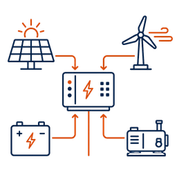
MET Optimization

Optical voltage, wind power, energy storage, diesel power coordinated.
Layer protection and control

From equipment to the network, a layer of autonomy and chain control is achieved.
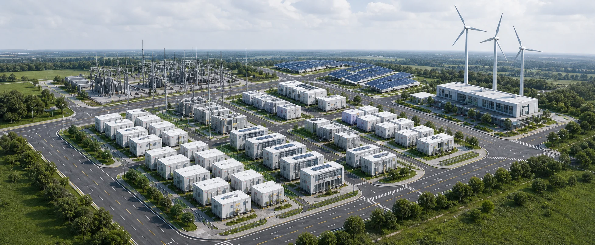
Microgrid assets and borders

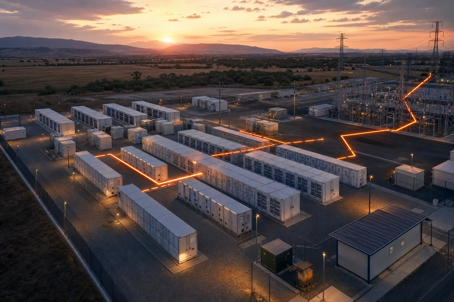
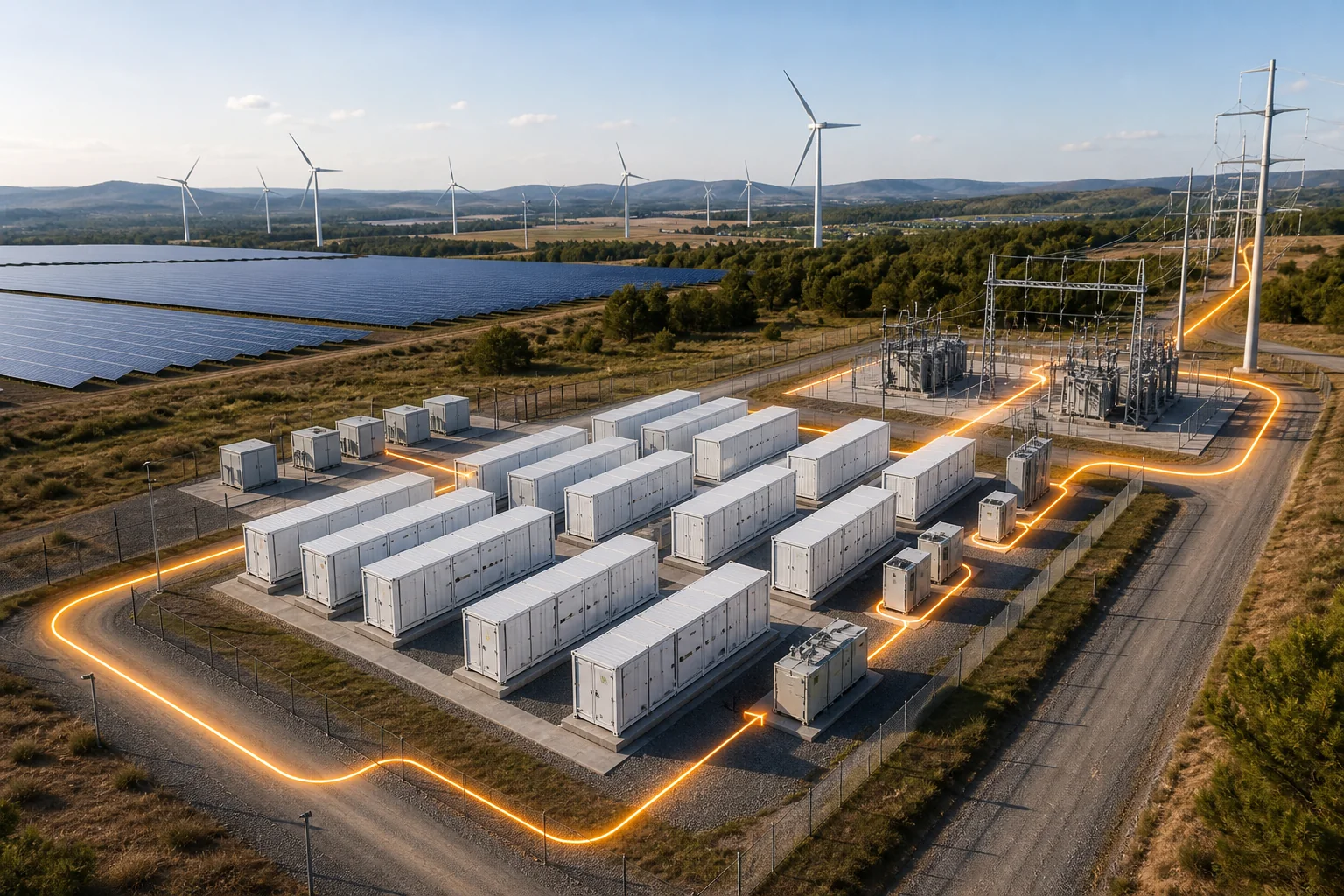
Microgrid site with storage containers, substation, PV array, and wind turbines

02 / Status Machine Five-state operating machines (same set of assets, different operating status)

01

Networking

Microgrid status icon run on-line
Trigger condition
Normal connection
Right of control
MGC-A Master
Load Status
All loads online
Standby capacity
2.0 MW(16%)
Exit Conditions
—
02

Plan separation

Microgrid status as planned for separation
Trigger condition
Planned overhaul/ schedule command
Right of control
MGC-A Master
Load Status
Load smooth transition
Standby capacity
2.2 MW(18%)
Exit Conditions
Separation complete.
03

Unplanned island

Microgrid's Unplanned Landscape
Trigger condition
Network failure / protection action
Right of control
MGC-A Master
Load Status
Scalp load
Standby capacity
1.8 MW(15%)
Exit Conditions
System stability
04

Black Start

Black-started Microgrid status indicator
Trigger condition
The whole station is out of power.
Right of control
MGC-A Master
Load Status
Gradual recovery of critical loads
Standby capacity
—
Exit Conditions
Critical load recovery
05

Reconnect

Microgrid status of reconnection
Trigger condition
Re-stabilize the network.
Right of control
MGC-A Master
Load Status
Gradual convergence of loads
Standby capacity
2.0 MW(16%)
Exit Conditions
Synchronization gate complete.
Power path. Normal Control / Data Protect / Chain

Microgrid stability comes from coordinating power, energy, and control time scales

Achorebo class <20ms

Protection and failure clearance, rapid current control and equipment cascade locks.

Relay protection/ quick control

milliseconds 20ms–200ms

The transformer reacts quickly, the voltage supports, power rings and inertial response.

PCS / Transform Control

Second 200ms–10s

Frequency, voltage recovery, one FM and rapid power coordination.

MGCC Rapid Control

min 10s–30min

Energy balance, optimization of movement, load recovery and energy storage power correction.

EMS / Energy Management

Hour >30min

Plan movement, capacity planning, demand forecasting and economic performance.

Planned / Forecast
1 ms 10 ms 100 ms 1 s 10 s 1 min 10 min 1 h

03 / Net I'm looking for the economy, I'm going to keep the island stable -- the same set of assets.

Networking: economic and binding optimization

Target: Minimize operating costs, meet netting constraints and plans

¥126,800 Cumulative daily cost of control
9.2 MW Projected peak load
48% Renewable energy penetration
6.0 MW Power purchase ceiling

Operation of the island: stability and security priority

Target: System frequency / voltage maintained and critical load power provided

49.5–50.5 Hz Frequency bandwidth
0.95–1.05 pu Voltage bandwidth
≥15% Standby capacity
Available Black Start

04 / Event Black Start An island incident log and black-start successful path

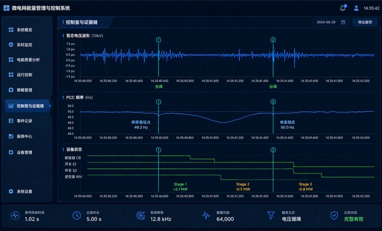
Unplanned island incident record

Records of voltage, frequency and storage power of unplanned isolated island events

Black Start sequence (success path and failure branch)

  1. 1Power on auxiliary powerDC / UPS StartPath
  2. 2Direct carrier prechargeBMS / PCS previewPath
  3. 3Networked BESS StartupCreate a middle-pressure matrixPath
  4. 4Distributive power activated.Wind / PhotovoltPath
  5. 5Critical load recoveryHospital / Communications / WaterPath
  6. 6Controlled load recoveryProcess / Office BuildingPath

Emergency: critical load maintained pending recovery
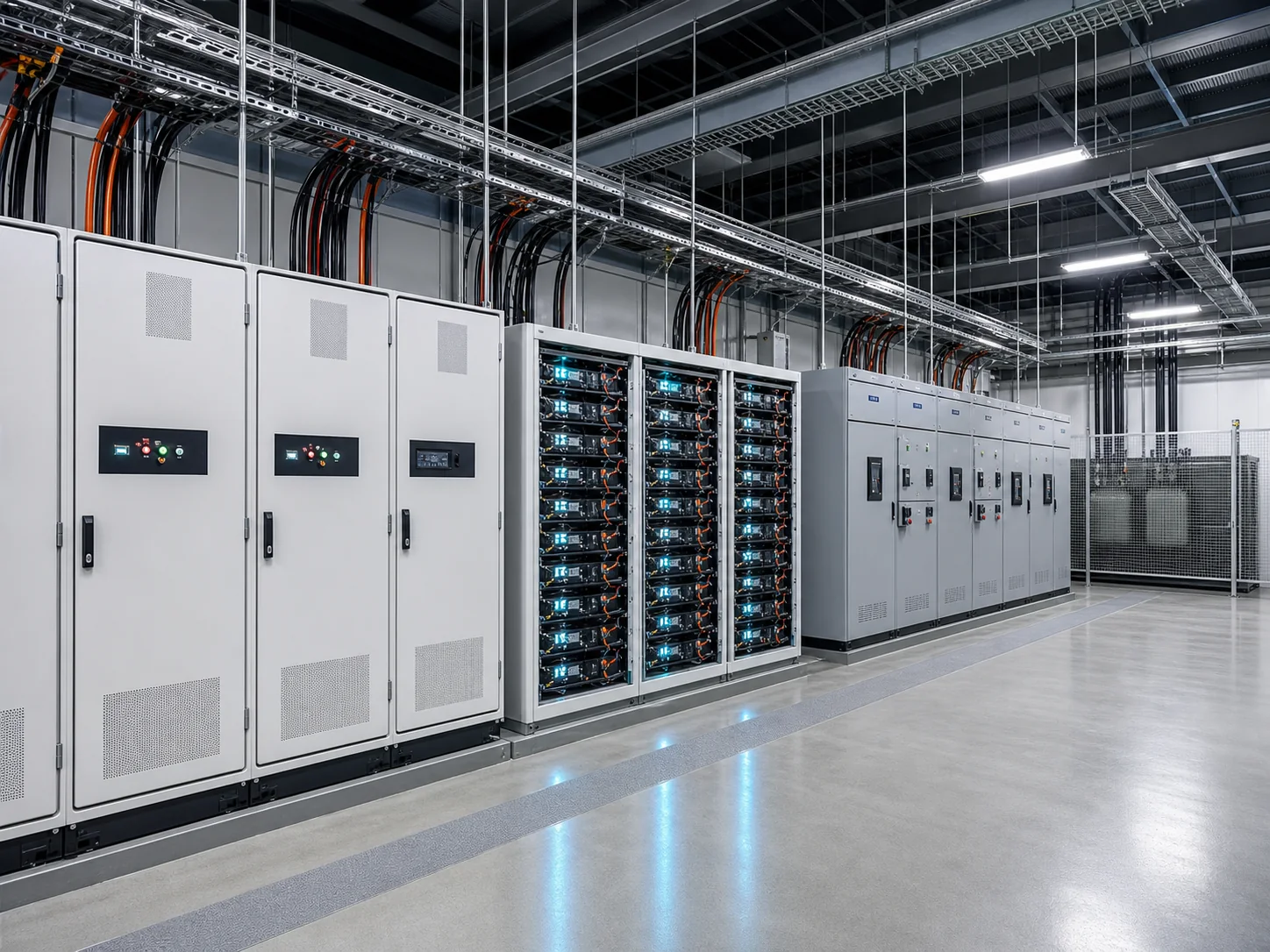
05 / Control Structure Layer control structure: distributed autonomy, centralized synergy

Device Layer PCS / BMS / Switch
PCS, BMS and Switches
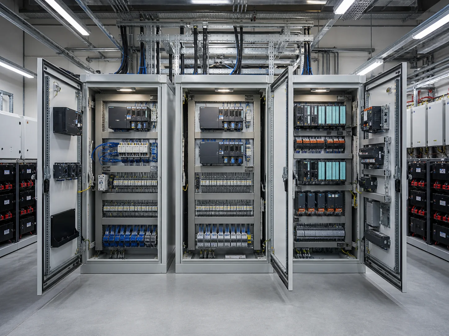
Local Control Layer LCU / RCS / PLC
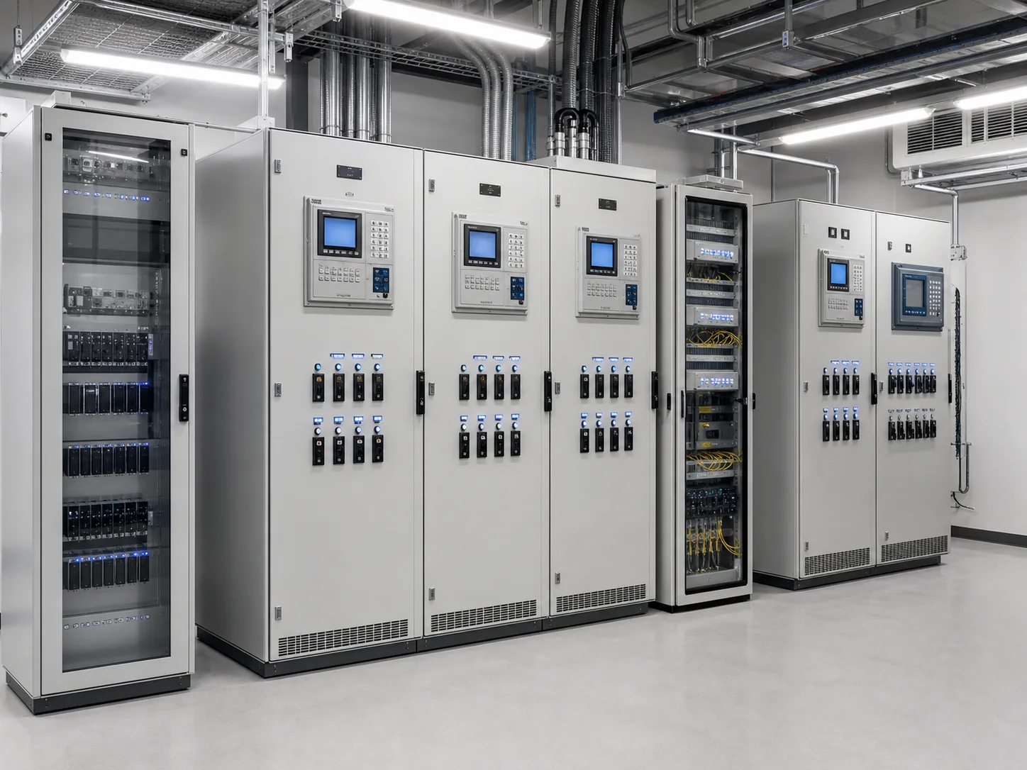
Local control level LCU, RCS and PLC control cabinet
Microgrid Control Layer MGCC Master / Ready
Microgrid Control Layer MGCC Master controller
Operational management EMS / SCADA
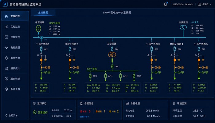
Operating Management EMS and SCADA Control Room
Protect Layer Protect / Chain
Protective layer relay protection and locking equipment
Transport and Operations Layer Operator / Engineer
Engineering maintenance workstation for the transport and operating layers
Control Object Device level Local Control Microgrid control Energy management Protect and Link
Typical cycle <100 ms 100 ms – 1 s 1 s – 1 min 1 min – 1 h <200 ms
Principal duties Real-time equipment control Local coordination Status Switch / Coordinate Economic dispatch Fault clearance
Redundancy policy Device-level redundancy controller double MGCC-A / B Redundancy of services Independent protection

06 / Storage / Load Multi-container power distribution and critical load stratification

Multi-container power distribution and health awareness (N+1)

Units Status SOC Temperature Available Power Health Command Power
BESS-01Online68%26°C2.3 MW98%0.8 MW
BESS-02Online65%27°C2.2 MW97%0.7 MW
BESS-03Online70%25°C2.3 MW98%0.8 MW
BESS-04Maintenance62%28°C0 MW96%0 MW
BESS-05Online66%26°C2.2 MW97%0.7 MW
BESS-06Online64%27°C2.1 MW97%0.7 MW
BESS-07Online69%25°C2.3 MW98%0.8 MW
  • Total available power13.4 MW
  • Current command power4.5 MW
  • N+1 Redundancy2.3 MW

Key load priority and scalding load matrix

Priority Example load Capacity Urgent reservation Cut order Restore Order Remarks
P1Life safety load0.8 MWReservations——Uncut.
P2Core Process1.2 MWReservations——Organisation
P3Control / Communications0.6 MWReservations——Standing insurance
P4Critical heating0.9 MWConditional13Conditions are appropriate.
P5Production support1.1 MWCut24Cut
P6Office / Support1.0 MWCut35Cut
P7Non-critical load1.6 MWCut46Downgraded
  • The level of security on the island4.3 MW
  • Current load4.1 MW
  • Residual0.2 MW

07 / Degraded scene Fault / Degraded scene and autonomy strategy

Interrupt communication

Path: Local autonomy

Policy: LSOP to remain secure

Control failure.

Switch: MGC-B takes over

Policy: Hot Ready / State Sync

PCS failure/absorption

Isolation: isolate the faulty unit

Policy: N+1 and redundancy

Generator failure

Policy: Start Logic Switch

Strategy: Bridge mechanism

Photovoltaic velocity

Strategy: Storage can calm down

Strategy: Power balance

SOC Too low

Policy: Load removal

Policy: Stop discharge

Protect Actions

Segregation: breakdown isolation

Policy: Partition Run
  • Autoprotect / Lock
  • Local autonomy
  • Artificial intervention
  • System Deduction Operation

08 / Site Engineering layout and control room evidence chain

Engineering design and scale expansion

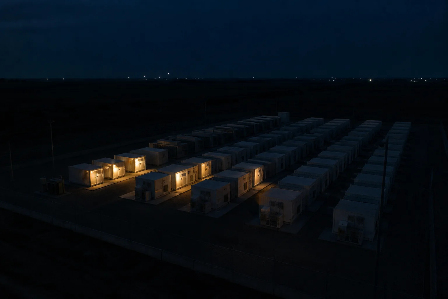
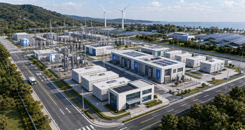
Container BESS site engineering layout
  1. 01BESS Container AreaFire interval 3 m
  2. 02MV Device ModuleSwitcher / transformer
  3. 03Container fire systemFire / Spray
  4. 04Cable Trench / BridgePower / Weak Separation
  5. 05Roads and firewaysChannel width 6 m
  6. 06Drainage and Noise DesignConstruction and acoustic measures
  7. 07Expand reserved spacePhase 2 set aside
  8. 08Maintenance and repair of corridorsTransport.

Control room and chain of evidence

Microgrid SCADA Control Room Surveillance

Evidence and records

  • One FM/ RV
  • Accidents and incidents
  • SOE Sequence Events
  • Trends and statements
  • Control policy trajectory
  • Clock Sync Time

Control End and Status

  • MGC-A (Main)Running
  • MGC-B (prepared)Stand by.
  • EMS / SCADA&Normal
  • Protection and monitoring&Normal
  • Networks and communications&Normal

System Time

System integration: normal

09 / Receiving and Inspection Validation and acceptance procedures System-level integration validation

Phase Test Object Verify Target Typical method Result
Device Level FAT PCS / BMS / Switch Device Equipment functionality and communication integrity I/O, protection, communication, chain testing Pass.
Control Level FAT PLC / LCU / MGCC Control logic-state switching Simulation injection, abnormal simulation Pass.
System Level SAT EMS / SCADA / Micronet Full station co-operation capability Networking, islanding, black-starting. Pass.
It's an island test. PCC / BESS / Load Frequency and voltage Stability Fault cut, load disturbance. Pass.
Reconnection Test MGCC / PCC Netting and smoothing back over the same period Angle, frequency, voltage differential verification Pass.

NEXT STEP

Combine boundary and delivery path around Microgrid & Containerrized BESS

Programme configuration and implementation tempo can be further confirmed on the basis of on-site loads, netting conditions, installed space and transportation requirements.