


Integrated lithium battery energy storage solutions
LIQUID COOLING & THERMAL MANAGEMENT

From heat source to heat-rejection boundary,
make temperature distribution a designable system parameter

For large battery energy storage systems, design from cell heat generation, cold-plate heat exchange, and rack hydraulic balance through CDU, chiller, and ambient heat-rejection boundaries—using closed-loop control of temperature, flow, pressure, and dew point so thermal management becomes a calculable, verifiable, and recoverable system capability.

ΔT
≤2.5°C Maximum temperature difference inside the cabinet
Temp
30–55°C Working temperature range
Effect
>95% Full season availability

From cell heat source to ambient heat dispersion boundary

Cold
Coolant 30–40°C
Answer.
Thermal interface TIM / Cold Plate
Board
ColdPlate 33–40°C
Expenditure
Branch 20–35°C
Set
Manifold 29–34°C
Hotwater
Coldwater
Heat load. 215 kW
System 8.3°C
System traffic 520 L/min
System pressure variance 48 kPa
Water temperature 36.0°C
Ambient temperature 28.0°C
Safe Temperature 21.0°C

Thermal and heat resistance maps

Starting with the core heating, an equivalent heat resistance network is being established, which identifies each layer of material and the heat-replacement path.

Inner temperature layer and balance

Compare front and side view heat fields, check the hot zone, temperature differentials and vertical gradients.

Liquid Cooling System overview: full closed loops from heat source to dispersed heat boundary Harmonizing cooling circuits, flows, pressures and the environment Change Hot

Environment
Ambient
BMS
Heat Management controller TMC
EMS
System efficiency 35%
System traffic 520 L/min
System pressure variance 48 kPa
System airflow 16.5 kW
Thermal dissipation 230 kW
CDU, water out. 36.0°C
Safe Temperature 21.0°C

Cold panel contact and module heat transfer path

Low thermal resistance design, controls the temperature rise between heat sources and cooling fluids.

Rθ ≤0.12
K·cm²/W

Multi-chamber flow/ pressure balance

Air - Liquid Convergence and Environment for Heating

Air-cooling scheme Wind-to-heat, which applies to a more mild environment.
Water cooling programme Water-cooled circuits are coordinated with outdoor heating equipment.

Heat load and power consumption

Condensation and dew-point control

Ambient temperature 28.0°C
Relative humidity 60%RH
Show some. 15.0°C
Water temperature 36.0°C
Safety balance 21.0°C

EMS / BMS / thermal-management closed-loop control

Pick Sensor Input Temperature
Pressure
Traffic
Humidity
↔
TMC Heat management controller Pump valve control
Fan control
Cold water crew
Show some policy
↔
BMS BMS SOC / SOH
Battery temperature
Health status
↔
EMS EMS Power dispatch
Policy down.
Energy Run

Extreme environmental adaptation

Hot 50°C High temperature environment
Cold -20°C Temperature
Wet 95%RH High-wet environment
High 4000 m Altitude

Balance between energy efficiency and life expectancy

Energy consumption throughout the year 28.7 MWh
Auxiliary energy consumption ratio 6.2%
Mean core temperature 39.1°C
Life expectancy increases +18%

Thermal management failure monitoring, positioning and self-healing: closed loops from anomaly to recovery

Anomalous discovery.

Sensor recognition traffic, pressure or temperature variability.

Root positioning

Anomalous circuits combined with secondary traffic, temperature and valves.

Branch 1&Normal
Branch 2Unusual
Branch 3&Normal
Branch 4&Normal

Strategy Execution

Adjust the speed of pumps, valve openings and cooling distribution.

Runback

Temperature and flow are restored to normal controlable areas.

Event Record

Automatically generate event evidence, parameters and action logs.

10:22:31Unusual
10:22:34Positioning
10:22:36Implementation
10:23:08Restore

Simulation Drive Design Validation

CFFD+system imitation + stage validation, shortening the design iterative cycle.

CFCD Thermal Simulation
System Simulation I/O
Structure / Package Validation

Engineering deliverables

Hot Thermal design reports Thermal load and boundary
P&ID P&ID and BOM Return route and equipment list
Complex Control logic statement Pump/valve / fan strategy
V Transport Manual Diagnosis and maintenance

Application Scenarios

Cover different capacity sizes and environmental conditions.

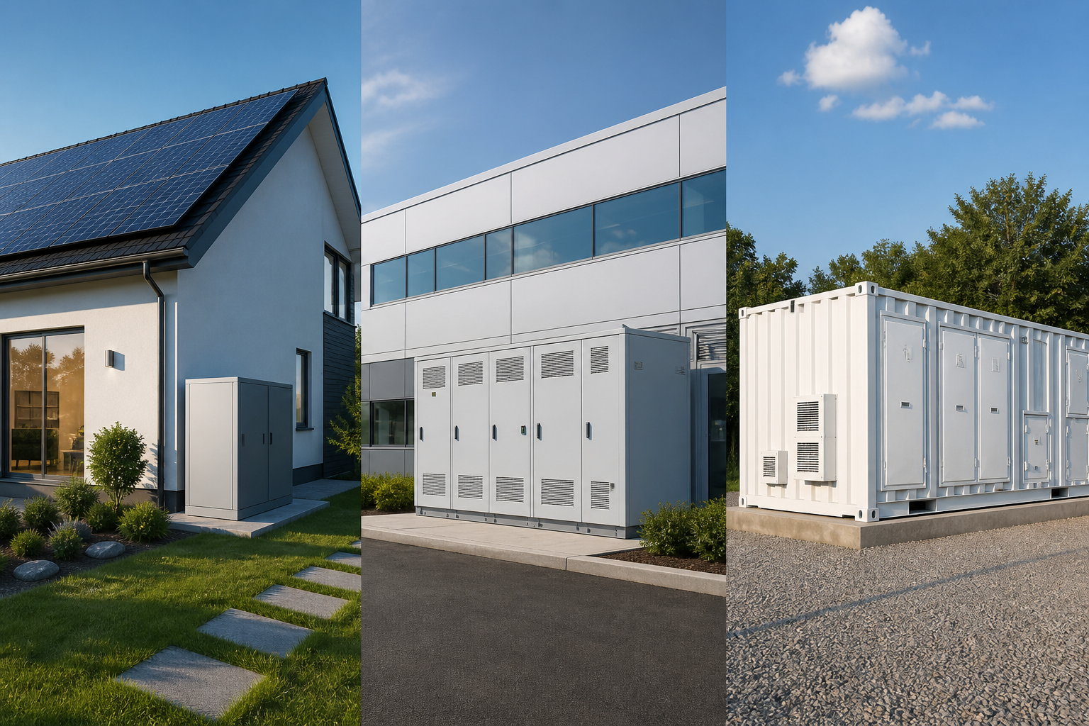
Source Network Side Storage
Commercial & Industrial Energy Storage
Independent storage power plants